Engine Combustion Pressure Analysis Systems
“More than high end dynamometer testing…”
In Cylinder Pressures (ICP)
In an effort to take product development to a new level DBR has invested in OEM type R&D procedures.
Put on “Superman” vision
By measuring the pressure inside a cylinder combustion chamber while an engine is running, very accurate data of the combustion process can be analyzed. This process called ICP is what we call “Superman” vision into a running engine. This ultra high-speed phenomenon allows data to be logged, viewed and analyzed in detail. The data can be displayed and analyzed relative to crankshaft/piston position in degrees. This procedure delivers the evidence, good and bad. Once you have used this technology, it is hard to run tests without it. DBR has since invested heavily in this technology and has been actively using this hardware/software to help create reliable race winning products.
Combustion pressure analysis has been around for quite a number of years. Originally this technology was only available in Formula 1. Today, ICP is used in all forms of motor sports including F1, NASCAR, Moto GP, endurance sports car racing and drag racing.
Companies like Kistler and AVL have provided very sophisticated testing equipment to OEM engine manufacturers for decades. Only within the last 10 years has ICP been available to general public. Since its release, it has allowed the average person to access this otherwise unobtainable data without a need for a PhD to understand it.
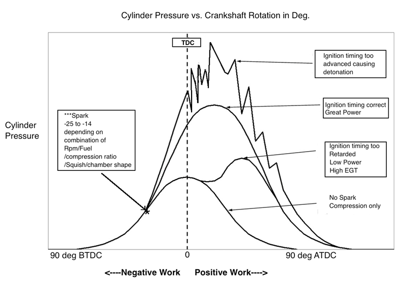
The graph below plots cylinder pressure versus crankshaft rotation. The cylinder pressure starts to rise as the piston moves upward starting compression. At the right moment, usually around 14 to 25 degrees before top dead center (TDC), the ignition system sends voltage to the spark plug. Once combustion starts, the pressure rises rapidly and peaks after TDC. This puts maximum pressure on the piston when the connecting rod is at the best leverage angle (around 15 degrees ATDC) to the crankshaft. During the power stroke the combusted gases expand rapidly and push hard on the piston. At a certain point the exhaust port opens and vents off the pressure in the cylinder, meaning no more “work” is being done. This all sounds very simple but it is amazingly complex as incredible physics and chemistry take place in a very short period of time. Utilization of ICP helps us maximize ignition and fuel calibration.
All multi cylinder engines may have varying pressure from cylinder to cylinder. No matter how hard you work to ensure that combustion chamber shape, volume, squish, ignition, timing, and AFR are all identical… the difference from one cylinder to the next can be significant. Some outboard engines have as much as a 15 hp difference from one cylinder to the next. Unfortunately this significant difference not only can be caused by the sharing of a common exhaust system but also by the result of the individual characteristics of ring seal per cylinder. Good ring seal equals more pumped air. Bad seal equals less pumped air. It is important to establish perfect ring seal before accurate engine calibration is attempted.
Being aware of these possible differences from cylinder to cylinder are invaluable. A cylinder with a higher or lower pressure can reduce the performance and speed of other cylinders, resulting in less torque and horsepower. Equalizing cylinder pressure not only can provide performance gains but increase reliability as well. During a basic ICP sweep, peak pressure location and the location of where the bulk of the mixture is burned is identified and located by individual cylinder and crankshaft rotation in degrees. This is invaluable for calibration! It is very common to end up with six individual maps for both ignition and fuel in an outboard engine. The days of a flat 24 degree ignition curve are gone.
In Port Pressures (IPP)
This same technology is used to record and analyze engine port pressures relative to crankshaft rotation. High-speed port pressure sensors effectively provide a “LOOK” into the intake and exhaust ports in real time.
Port pressures, displayed and analyzed relative to crankshaft/piston position, allow us to make critical decisions related to the engine's intake, exhaust system and port timing. Again this is invaluable as it helps us pick proper reed valves, port timing and tuner combinations that are powerful yet reliable.
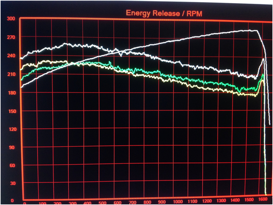
Below is the energy release graph for cylinders 1, 3, 5 on an outboard engine versus RPM. It is very apparent in the graph that one cylinder out performs the others. The goal is to try to equalize power output among cylinders.


